
Upgraded Digital Keytag Door Controller - Installation Guide
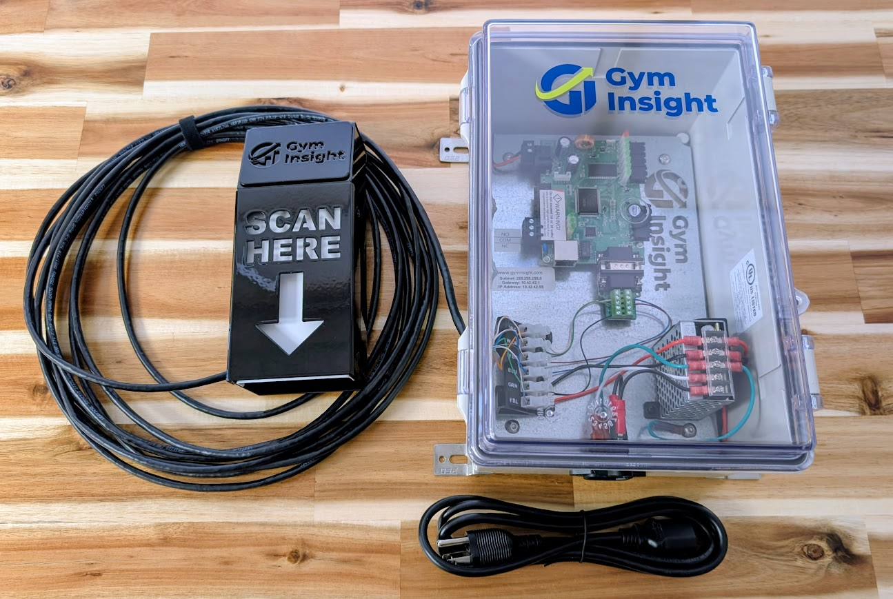
Before installing, please conduct a bench test with Gym Insight, to ensure that everything is working. A bench test must be performed on the controller hardware prior to installing, or else the warranty will be voided. Call (855) 367-4967 or email [email protected], and we will be happy assist you in completing the bench test and answer all of your questions.
Gym Insight provides support for all the hardware that we sell. Some hardware and services will be needed that we do not provide, and include: a licensed low voltage installer, the locking device, wire and cable, a Windows PC, and network Administrator access.
We highly recommend scheduling your installation during normal support hours, in order to better assist you.
Scanner Installation
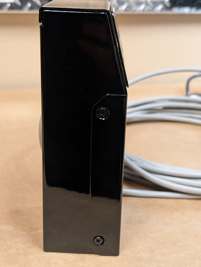
Remove the four M4 screws securing the cover of the scanner enclosure to remove the cover.
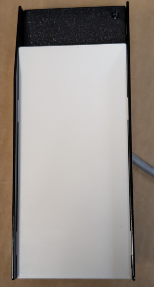
Remove the white plate by sliding it out of the notches.
Remove the M3 screws to remove the waterproof cover.
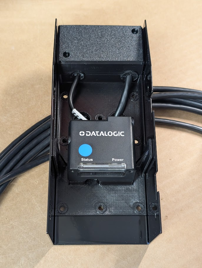
Unplug and remove the cable for now. You will reconnect the cable once the enclosure has been mounted.
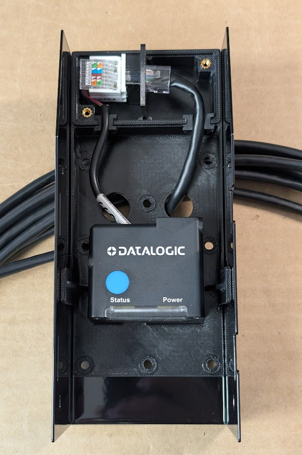
The scanner in its enclosure is ideally designed to be mounted on a single gang switch box, through which the cable is routed. Alternately, it can be mullion-mounted on either the left or right side of the door using the alternate screw holes.
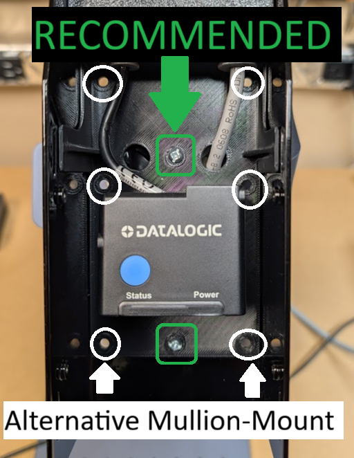
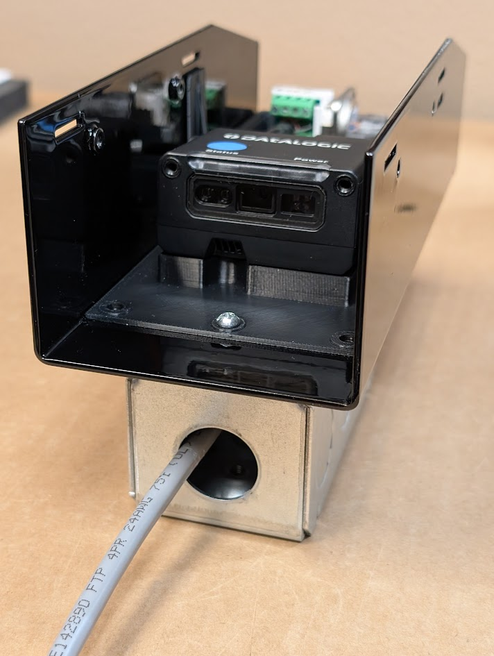
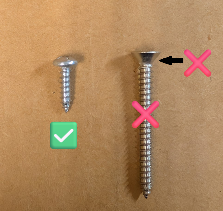
⚠️WARNING: USE FLAT BACK SCREWS (i.e., SHEET METAL OR TRUSS HEAD SCREWS) FOR MOUNTING TO THE WALL OR MULLION. DO NOT USE TAPERED SCREW HEADS AS THEY WILL CRACK THE PLASTIC AND VOID THE WARRANTY.
Route the entire scanner's cable through the enclosure hole and all the way to the door controller.
Reattach the Ethernet jack back into the from the scanner to the door controller.
Insert the scanner's cable through the hole, without the knockout.
Replace the knockout to secure the scanner cable.
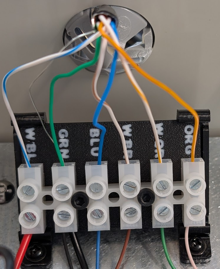
Connect the leads in accordance with the labels, as shown. (TIA 568-B RJ45 color coding system is used.)
- ORG = Orange
- W OR = White with orange stripe
- W BR = White with brown stripe
- BLU = Blue
- GRN = Green and Silver/Shield
- W BL = White with blue stripe
Door Lock Connection
Connect the door locking device to the NO | COM | NC terminal block as shown.
For Maglock locks:
| Terminal | meaning |
| NC | Normally Closed |
| COM | Common |
For Strike locks:
| Terminal | meaning |
| NO | Normally Open |
| COM | Common |
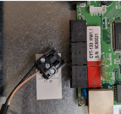
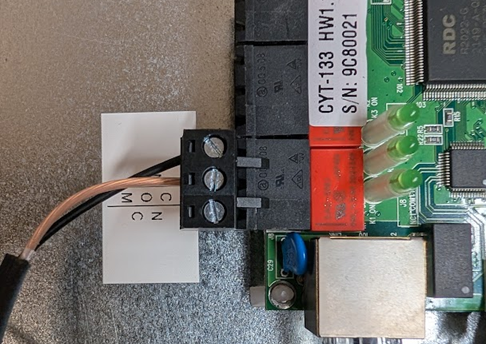
NOTE: THIS DOES NOT SUPPLY POWER TO THE LOCK. A SEPARATE POWER SUPPLY, RATED FOR THE LOCKING DEVICE, MUST BE PROVIDED TO POWER THE LOCK.
⚠️ WARNING: Do not exceed 1A or 30V across the relay connections. If your locking device exceeds 1A or 30V, you will need to add a high current relay that meets or exceeds the lock manufacturer’s specifications. For example: if you are using a magnetic lock that is rated at 1200mA (1.2A), you will need to use an additional relay, or the device will be irreparably damaged.
Computer Connection
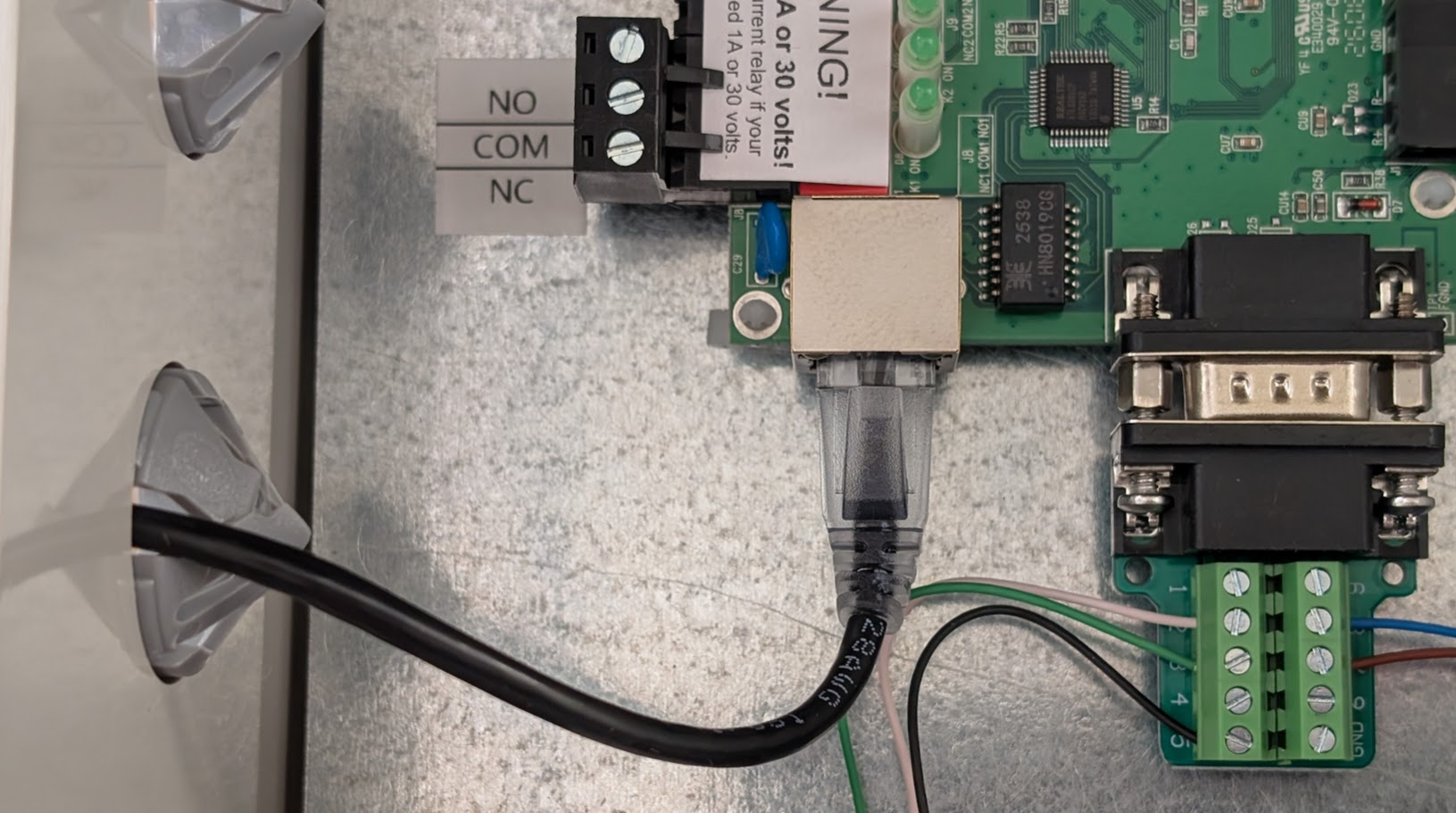
Insert the network cable through the hole in the side of the enclosure and into the Ethernet jack at the bottom of the control board (see picture below). Replace the knockout.
Finishing Touches
Close and latch the Access Controller cover lid.